By Anurag Rathore, Vijesh Kumar
 Among the various downstream processing unit operations that are used for purification of biotech products, chromatography is uniquely capable of providing resolution between a product and other closely related product variants and impurities. This specificity is of particular relevance to the production of biotech therapeutics, which require high standards of purity. However, development and optimization of a process chromatography step presents a major challenge due to the large number of process parameters that can affect the performance of the step. For example, for the commonly used ion-exchange chromatography, pH, ion concentration, gradient, and stationary phase can affect the recovery step as well as the resulting product quality.
For complex unit operations such as process chromatography, mechanistic modeling can assist in developing a systematic approach for process development, monitoring, and control. Models can also be judiciously used to reduce lab experimentation, thereby significantly reducing the time required and the cost incurred during process development. With the advent of quality by design, there have been renewed efforts toward gaining a deeper process understanding through mechanistic modeling of key bioprocess unit operations.
Researchers have attempted a variety of approaches to chromatography modeling. The basic requirement for a good model is for it to be predictive and be able to explain at least most of the variability in the data. In addition, the model should be feasible for implementation in an industrial environment. Modeling approaches that are commonly used can be broadly classified into two categories. The first category, empirical modeling, is where the model is built using experimental data based on approaches such as the design of experiments (DOE). The second category is mechanistic modeling, where the model is built on the underlying fundamental processes of the system. DOE-based approaches dominate modeling efforts in industry and can be quite effective at offering process knowledge and determining the design space. However, because they do not incorporate the underlying mechanisms, empirical models suffer with respect to accuracy and robustness. In contrast, mechanistic models provide excellent predictability. While they are preferred over empirical models, the complexity of most chromatography operations does not lend itself to mechanistic modeling and hybridization of the mechanistic model. Traditional approaches of mechanistic modeling require so much experimental data that their use in industry is severely limited.
In general, models are used for prediction and optimization of the process outputs such as breakthrough or elution profile. A detailed investigation is often required to examine how the retention behavior and capacity vary as a function of the different process variables. Apart from the prediction of the retention and peak profile, mechanistic models can also be used to develop an efficient optimization strategy and for robustness testing of the gradient elution in chromatography.
Prerequisites for modeling
With the recent advancement of efficient numerical methods, it is feasible to create a complex and detailed mechanistic model that is capable of describing mass transfer at the bead level for a chromatography resin and can be executed using a personal computer. Ion-exchange chromatography (IEC) is a major workhorse for purification of biotherapeutics. Development of a mechanistic model requires three major steps: modeling of mass transfer, modeling of binding, and finally, validation of the mechanistic model. The choice of details depends on the desired predictability.
Mass-transfer models
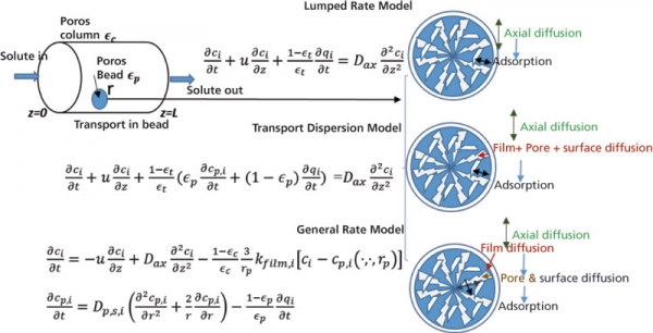
The transport of solute through the various phases inside the packed bed column has been described using mathematical models, albeit with different level of details (1). Mechanistic modeling requires the solution of mass balance equations, which are typically achieved using numerical methods (2). As desired accuracy increases, resource requirements for the numerical solution of the partial differential equations obtained for the model also increase. Broadly, there can be four boundaries for mass transfer limitations at the bead level, namely, external mass transfer through the film layer (kfilm) around the bead particle, diffusion through the pore (Dpore) and surface (Ds) of the bead, and reaction rate at the binding site. A complete description of mass transfer models is available in the form of the general rate model (GRM), which covers kfilm, Dpore, Ds, and reaction rate (1, 3–4). However, a numerical solution of the GRM is computationally intensive. With the availability of new, optimized numerical solvers and ready-made tools, such as CADET and chromX, the past decade has seen an increase in usage of GRM researchers (5, 6). Many researchers have instead chosen to use less complex models, such as the transport dispersive model (TDM) (711). In this model, the internal and external mass transfer resistances are lumped into one effective transfer coefficient. The next simplest model in the hierarchy is the lumped rate model (LRM) (12–16). In this model, rate kinetics and mass transport are lumped in a single parameter and diffusion in pore and solid is assumed to be infinite. LRM is the simplest model that has been widely used to model IEC. The commonly used equations and their associated conditions are depicted in Figure 1.
 Figure 1: Schematic representation of the transport of a solute through a bead particle within a column.
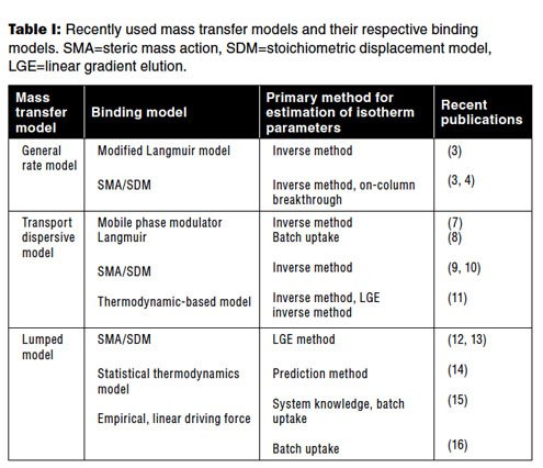
A key aspect in modeling of IEC is that of the choice of model for protein binding. There are dozens of adsorption models available in the literature. Most of the models are based on either the Langmuir model or the stoichiometric displacement model (SDM) (17). Among the Langmuir models, the mobile phase modulator model for salt-based ion-exchange systems are more common (7, 8). The steric mass-action model is a common choice for a stoichiometric displacement model (4, 9–10, 12–13). Thermodynamic-based adsorption models that are based on Mollerup’s formulation have also been used by many researchers (18). Recently, pH and temperature dependence have also been incorporated into this model (13). A more detailed model based on molecular structure has also been applied recently (14). If none of the binding models is able to sufficiently model the data, then empirical models can also be used (16). Table I presents a summary of the different models and their use in recent publications. The choice of the binding model is mostly driven by how easy and accurate it is in determining the model parameters.
 Table I: Recently used mass transfer models and their respective binding models. SMA=steric mass action, SDM=stoichiometric displacement model, LGE=linear gradient elution.
Estimation of model parameters
The greatest challenge in development of a model lies in gathering accurate estimates of the various parameters used in the model. Model parameters can be divided into three broad categories, namely, column parameters, mass transfer coefficients, and binding parameters. Column parameters are mainly reaction-independent and are easy to determine. They consist of column and pore porosities. Typically, these porosities are estimated using a non-binding condition of protein sample or a suitable tracer. The second category is that of mass transfer coefficients. These consist of column axial dispersion (Dax) , kfilm, Dpore, and Ds. If GRM is not used, then a separate estimation of Dpore and Ds is not needed. The rest of the mass transfer coefficients can be estimated using the height equivalent to a theoretical plate (HETP) method or the Yamamoto linear gradient elution (LGE) method (12–13). There is no specific method for estimating Dpore and Ds for the GRM. In most cases, a theoretical estimation or inverse fit method is used. The binding parameters are estimated using off-column uptake batch experiments or on-column pulse injection and elution through step or gradient of the mobile phase modulator. The rough estimation can be made from retention of peak maxima and can be further refined using the inverse fit method.
Both the methods of off-column and on-column estimation of binding parameters have their benefits and shortcomings. While the uptake batch experiments are easy to perform and do not interfere with the mass-transfer parameters, this approach lacks accuracy in samples with a very low concentration of solutes. The measurements are accurate for the on-column methods, but these methods suffer from interference towards measurement of the mass transfer parameters. A summary of the different, recently used mass-transfer and binding models is tabulated in Table I. In the following section, a case study of of a monoclonal antibody (mAb) in an IEC model is presented.
Mechanistic modeling for development of an ion-exchange chromatography step to purify mAbs
In this section, the authors provide a step-wise method to build an ion-exchange mechanistic model using open-source chromatography design and analysis tool (CADET, https://github.com/modsim/CADET). The mechanistic model used in this approach is GRM with an extended Langmuir model that has salt as mobile phase modulator (3).

The parameters are determined using inverse method (3). It is important in this method that all the dead and delay volumes be included in the model to depict the actual retention time and account for dispersion in the chromatograph and column band broadening separately. For example, tubings and detector dead volumes can be modeled as a series of dispersed plug flow and continuous stirred-tank reactors. A typical setup is shown in Figure 2 and has been described in more detail in the literature (3). Once the model has been set along with CADET, steps for determination of the model parameters are as follows.
Step 1: Estimation of Äkta chromatograph parameters
A zero-volume connector should be used to determine the flow parameters for the external volume of the Äkta chromatograph (Cytiva), in place of the column. Protein samples can then be injected to generate the output flow profile without the column. This profile can be used to calculate dispersion and the residence time of the tubing, the mixture, and the detector for the system.
Step 2: Estimation of column flow parameters
Once system parameters are estimated, a packed column of a bed height of 5 cm can be connected. Protein samples then can be injected with high Na+ content so that the protein does not interact with the resin (non-binding condition). The resulting data can be used to calculate column porosities and dispersion by fitting the output profile with the estimated profile using CADET simulation with trial values of the parameter.
Alternatively, a suitable tracer—one that is a smaller size than the bead pores and another that is bigger than the pore size—can be injected, and porosity can be directly calculated from the retention time of the tracers. The axial dispersion coefficient can be estimated using HETP (height equivalent to a theoretical plate) plots at different flow velocities.
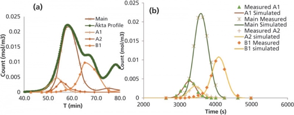
Step 3: Estimation of mass-transfer parameters and binding parametersThe binding parameters and internal mass-transfer coefficients can be estimated via injection of the protein samples. The outlet profile can be obtained with combinations of step and gradient elution. Because a mAb product may contain different variants, it is important to isolate the individual variants peak, or peaks can be reconstructed for individual variants using the high-performance liquid chromatography (HPLC) analysis from fractions collected (Figure 3). The reconstructed peak can then be used to fit the simulated profile with the trial parameters values fed in CADET. The adsorption and transport parameters trial values can be estimated using Henry’s plot for step elution at various salt concentrations. The pore diffusion can be estimated using correlations available in the literature between free diffusion and pore diffusivity.

Figure 3: Modeling of separation of charge variants following ion-exchange process chromatography. The graph in (A) shows the reconstruction of a peak from high-performance liquid chromatography analysis, and (B) illustrates a typical simulation. A1 and A2 are acidic variants; B1 is basic variant.
Alternatively, batch uptake experiments can be done for the isolated peaks, and adsorption isotherm data can be fit to determine the parameters. The problem with this method would be obtaining sufficient quantities of pure isolated variants, as some of the variants may be present in a small amount and merge with other variants.
Step 4: Model validationModel validation can be performed by using a lab-scale column of the same bed height as in a commercial column and running it at various protein loadings to cover the likely range of operation. The elution gradients should also be tested for a range of shallowness. At very shallow gradient or very low step, the model may not offer accurate predictions, because diffusivity coefficients may not be constant at extreme ionic concentrations.
Step 5: Process optimization
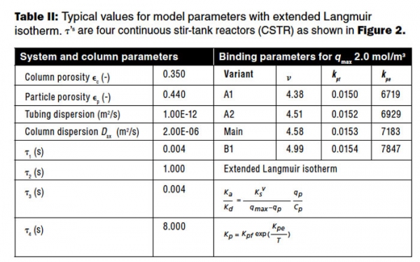
Once the model and model parameters are established, process optimization studies can be performed to achieve optimal selectivity and yield. The typical values for the model parameters calibrated from inverse method are listed in Table II for reference. Reconstructed peak shape for variants and its fit are also shown in Figure 2. The fit shows excellent agreement to the experimental data. Prediction of elution of the main component is more accurate than that of the smaller variants. The overall residual error was less than 0.01.

Use of mechanistic modeling in the biotech industry
As seen in the aforementioned case study, predictions for a complex, four-component system can be achieved with high accuracy using the inverse method for determination of model parameters. This approach is feasible for current models due to the availability of efficient numerical methods. A typical simulation can be completed in less than 5 minutes (on an Intel i7 Desktop PC), even for detailed general rate models. Simulations enable the parameters to be estimated directly from the process chromatograms. Most of the older approaches were tedious and largely dependent on batch uptake data. Older approaches, coupled with the relatively inefficient numerical approaches, are viewed as too resource- and time-intensive to be useful in an industrial environment.
Conclusion
The need for new developments to understand adsorption behavior at extreme load capacity exists. Resin structures and chemistry will continue to evolve, and many advancements have been made in the past decade that have made the use of mechanistic modeling for achieving efficient manufacturing possible.
Mechanistic modeling can also be used to perform sensitivity analysis to assess the impact of various input process variables on outputs. Modeling can make process robustness studies more efficient, aid process monitoring efforts, and can facilitate implementation of process analytical technology (PAT). The authors believe the industry will see a rise in modeling during the next decade as the biotech industry attempts to institutionalize the principles of QbD and PAT and moves towards continuous processing.
References
1. E. von Lieres and J. Andersson, Comput. Chem. Eng. 34 (8), 1180–1191(2010).
2. I. H. Schmidt-Traub, M. Schulte, and A. Seidel-Morgenstern, “Modeling and Model Parameters,” in Preparative Chromatography, (Wiley-VCH verlag GmbH & Co. KgaA, 2nd ed., 2012), pp. 321–424.
3. V. Kumar et al., J. Chromatogr. A 1426, 140–153 (Nov. 21, 2015).
4. N. Borg et al., J. Chromatogr. A 1359, 170–181 (2014).
5. E. von Lieres et al., Chemie Ingenieur Technik 86 (9), 1626–1626 (2014).
6. T. Hahn et al., J. Chem. Educ. 92 (9), 1497–1502 (2015).
7. A. Sellberg et al., J. Chromatogr. A 1481, 73–81 (Jan. 19, 2017).
8. T. Ishihara et al., J. Chromatogr. A 1114 (1), 97–101 (2006).
9. N. Brestrich, T. Hahn, and J. Hubbuch, J. Chromatogr. A 1437, 158–167 (March 11, 2016).
10. J. Winderl, Johannes, T. Hahn, and J. Hubbuch, J. Chromatogr. A 1475, 18–30 (Dec. 2, 2016).
11. B.K. Nfor et al., Biotechnol. Bioeng. 109 (12), 3070–3083 (July 4, 2012).
12. M. Rüdt et al., J. Chromatogr. A 1413, 68–76 (Sept. 17, 2015).
13. S. Kluters et al., J. Sep. Sci. 39 (4), 663–675 (2016).
14. R. Khalaf et al., J. Chromatogr. A 1459, 67–77 (2016).
15. B. Guélat et al., J. Chromatogr. A 1447, 82–91 (2016).
16. A. Creasy, Arch, G. Barker, and G. Carta, Biotechnol. J., DOI: 10.1002/biot.201600636 (Jan. 24, 2017).
17. A.M. Lenhoff, Materials Today: Proceedings 3 (10), Part A, 3559–3567 (2016).
18. J.M. Mollerup, J. Chem. Eng. Data 59 (4), 991–998 (December 2013).
ALL FIGURES ARE COURTESY OF THE AUTHORS